Robotic Inspection of Automotive Spot Welds
A modern vehicle body can contain thousands of resistance spot welds. These small joints help hold together structural panels, closures, brackets, reinforcements, battery enclosures, and other sheet-metal assemblies.
A defective or missing spot weld can reduce joint strength, create dimensional problems, generate noise or vibration, and affect the long-term durability of the assembly. However, manually inspecting large numbers of welds is slow, repetitive, difficult to standardize, and often limited to sampling.
Robotic spot-weld inspection addresses this challenge by moving cameras, ultrasonic probes, laser sensors, or other inspection devices to programmed weld locations. The system captures inspection data, evaluates each weld against defined criteria, and records the result for traceability.
This guide explains how robotic inspection of automotive spot welds works, the technologies available, the defects that can be identified, and the factors manufacturers should consider before implementing an automated system.
What Is an Automotive Spot Weld?
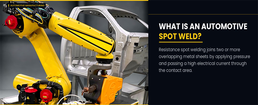
Resistance spot welding joins two or more overlapping metal sheets by applying pressure and passing a high electrical current through the contact area.
Electrical resistance generates heat at the interface between the sheets. The material melts locally and forms a weld nugget. The electrodes continue applying force while the material cools and solidifies.
Spot welding is widely used in automotive manufacturing because it is:
Spot-welding quality is influenced by many variables, including welding current, weld time, electrode force, electrode condition, sheet thickness, coatings, material composition, part fit-up, contamination, and electrical resistance.
Standards such as ISO 14373:2024 cover resistance spot welding of coated and uncoated low-carbon steels and address weld assessment, production testing, weld dimensions, strength, failure description, and visual examination. Applicable requirements vary by material, component, customer specification, and production location.
What Can Go Wrong with a Spot Weld?
A spot weld may appear acceptable from the outside while having an inadequate internal nugget. Conversely, a visible indentation or discoloration does not necessarily mean that the joint is defective.
Typical spot-weld conditions include:
Missing welds
A planned weld may not be produced because of robot-position errors, equipment faults, incorrect programming, part misalignment, or process interruptions.
Undersized weld nuggets
Insufficient heat or pressure can create a nugget smaller than the required size, reducing joint strength.
No-weld or stick-weld conditions
The electrode marks may be visible even though a proper metallurgical bond has not formed between the sheets.
Expulsion
Excessive current, poor fit-up, contamination, or other process conditions can force molten material out of the weld. Expulsion may leave spatter, pits, or an irregular surface and can reduce the effective weld size.
Burn-through
Excessive heat can create holes or severe surface damage in the sheet.
Excessive indentation
High electrode force, excessive heat, or worn electrode caps can create deep surface depressions.
Cracks and porosity
Cracks, internal voids, shrinkage cavities, or pores can affect the integrity of the weld.
Incorrect position
A weld may be present but placed too close to an edge, outside the intended overlap area, or away from its specified coordinate.
Electrode-related defects
Worn, misaligned, contaminated, or mushroomed electrodes can cause irregular weld impressions and inconsistent nugget formation.
Why Is Spot-Weld Inspection Difficult?
Spot welds present several inspection challenges.
First, their critical characteristics are partly internal. A standard camera can detect surface appearance but cannot directly measure a hidden weld nugget.
Second, automotive assemblies have complex three-dimensional geometries. Welds may be located on vertical surfaces, inside openings, near flanges, or in areas that are difficult for an operator or fixed sensor to access.
Third, surface appearance varies with:
Finally, the large number of welds makes complete manual inspection difficult. An automated inspection system must move quickly while maintaining accurate sensor positioning and reliable defect decisions.
What Is Robotic Spot-Weld Inspection?
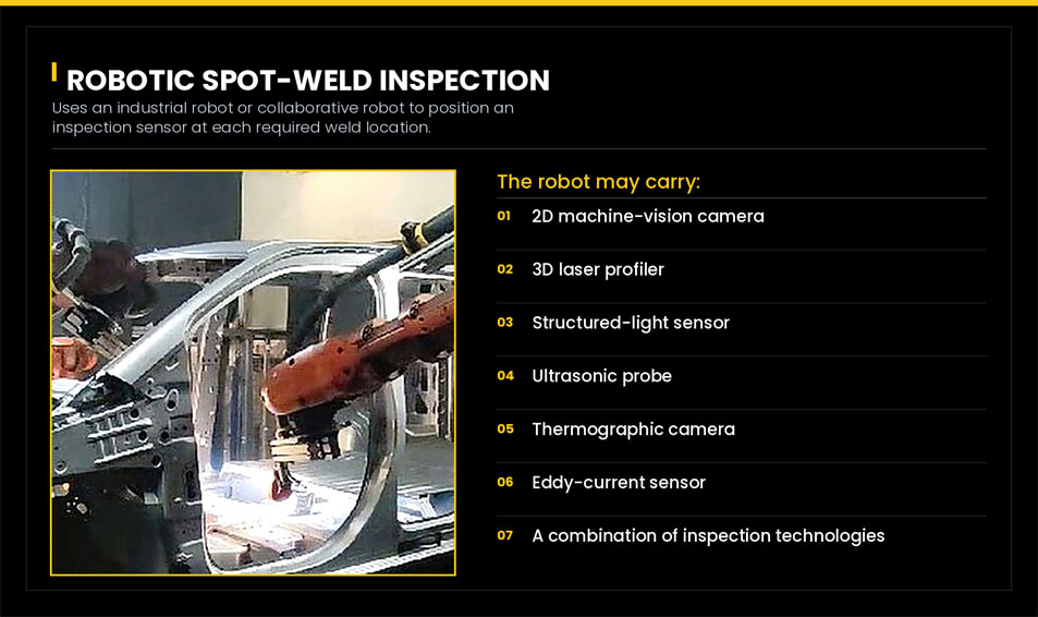
Robotic spot-weld inspection uses an industrial robot or collaborative robot to position an inspection sensor at each required weld location.
The robot may carry:
Alternatively, the robot may manipulate the automotive component in front of one or more stationary sensors.
A complete system coordinates robot motion, sensing, lighting, part positioning, inspection software, data storage, safety devices, and communication with the production line.
How a Robotic Spot-Weld Inspection System Works
Although the sequence varies by application, a typical system follows these steps.
Technologies Used for Robotic Spot-Weld Inspection
No single inspection method identifies every possible defect. Technology selection should begin with the specific quality characteristics that must be measured.
1. Robotic 2D machine-vision inspection
A robot-mounted camera captures controlled images of each weld surface. Image-processing or AI software analyzes visible characteristics, including weld presence, approximate position, electrode-mark shape, indentation, expulsion, spatter, burn-through, holes, visible cracking, surface contamination, and electrode-imprint consistency.
Advantages: non-contact inspection, short acquisition time, high-resolution surface records, inspection of many weld locations, relatively simple robot-mounted hardware, and useful for weld-presence and appearance verification.
Limitations: a camera evaluates visible surface evidence. It cannot directly confirm internal nugget diameter, internal bonding, porosity, or hidden cracks. Vision should therefore not be presented as proof of internal weld strength unless the relationship has been established through a validated quality study.
2. Robotic 3D laser profiling
A 3D laser profiler projects a laser line onto the weld area and measures the surface geometry. The robot moves the sensor over the weld, or the sensor captures profiles from a controlled position. The resulting 3D data can measure indentation depth, weld-impression diameter, surface height, crater geometry, edge location, expulsion-related deformation, and weld position relative to part features.
Advantages: quantitative surface measurement, less dependent on surface color than conventional imaging, effective for dimensional inspection, useful for detecting geometric deviations, and creates traceable 3D records.
Limitations: 3D profiling still measures the external surface. It does not directly reveal the complete internal nugget or interface condition. Reflective surfaces, steep angles, deep recesses, and obstructions can also affect data quality.
3. Robotic ultrasonic testing
Ultrasonic testing introduces high-frequency sound into the welded sheets. Reflections from material boundaries and the weld region are analyzed to estimate internal weld characteristics. A robot can position a specialized ultrasonic probe over each weld and control the inspection angle, contact, and force.
Ultrasonic spot-weld inspection may help evaluate weld nugget size, lack of bonding, stick welds, internal discontinuities, sheet interfaces, and some forms of porosity or abnormal fusion.
Specialized high-frequency probes are commonly used because spot welds are small and the joined sheets are thin. TWI notes that ultrasonic testing has been used in automotive applications as an indicator of weld size, while also emphasizing that signal interpretation requires expertise and correlation with destructive results. TWI's spot-weld NDT guidance describes this validation requirement.
Advantages: provides information about internal weld conditions, can reduce dependence on destructive sampling after validation, produces measurement data for traceability, and can be automated for repeatable probe placement.
Limitations: usually requires controlled probe contact, may require water or another coupling medium, sensitive to probe alignment and contact condition, complex signals require validated interpretation, surface geometry and coatings may affect inspection, cycle time may be longer than visual inspection, and correlation with destructive testing is essential.
4. Active thermography
Active thermography applies controlled thermal energy to the inspection area and monitors heat flow using an infrared camera. Subsurface bonding conditions influence how heat moves through the material. Abnormal thermal patterns may indicate differences in the weld region.
Advantages: non-contact measurement, potentially rapid area inspection, can inspect more than one weld within the field of view, and may identify subsurface differences that are not visually apparent.
Limitations: results depend on material, coating, thickness, geometry, and heating method. Environmental thermal variation must be controlled, complex assemblies may produce difficult-to-interpret heat patterns, and application-specific validation is required.
5. Eddy-current inspection
Eddy-current sensors induce electromagnetic fields in conductive material and analyze changes caused by geometry or material conditions. Potential applications include detecting surface or near-surface abnormalities and evaluating certain weld characteristics.
Advantages: non-contact or near-contact operation, no liquid couplant may be required, sensitive to electrical and material changes, and can be integrated with robotic scanning.
Limitations: sensitive to sensor distance and orientation, material properties and coatings affect results, complex geometry can complicate interpretation, and it may not provide a direct measurement of mechanical weld strength.
6. Process-data monitoring
Modern welding controllers can record parameters such as welding current, voltage, dynamic resistance, electrode force, weld time, electrode displacement, energy, cooling conditions, and equipment fault signals.
Process monitoring can detect abnormal welding cycles and provide immediate feedback. However, it evaluates how the weld was produced rather than directly examining the completed joint. Process data is most effective when combined with periodic or automated post-weld inspection.
Comparing Spot-Weld Inspection Methods
| Inspection method | Surface defects | Internal information | Contact required | Typical role |
|---|---|---|---|---|
| 2D machine vision | Strong | No direct measurement | No | Presence and appearance |
| 3D laser profiling | Strong dimensional data | No direct measurement | No | Indentation and surface geometry |
| Ultrasonic testing | Limited surface information | Strong potential | Usually yes | Internal nugget assessment |
| Active thermography | Surface and subsurface response | Application-dependent | No | Rapid comparative inspection |
| Eddy current | Surface and near-surface response | Application-dependent | No or near-contact | Specialized material assessment |
| Process monitoring | Indirect | Indirect | Built into welding process | Real-time process control |
| Destructive testing | Yes | Direct physical evidence | Destructive | Validation and audit testing |
The right solution may combine several methods. For example, machine vision can verify weld presence and surface condition, while ultrasonic testing evaluates selected welds for internal bonding.
The Role of AI in Spot-Weld Inspection
Traditional machine-vision systems use rules based on dimensions, contrast, edge position, intensity, shape, or surface height. These methods can perform well when weld appearance and imaging conditions are consistent.
AI-based vision can be helpful when acceptable welds exhibit natural variation that is difficult to describe using fixed thresholds. AI models may support:
What AI cannot do by itself
AI does not change the physical limits of the sensor. A model analyzing a 2D photograph cannot directly see a hidden weld nugget. It may identify surface patterns correlated with certain internal conditions, but that relationship must be demonstrated using representative production data and an appropriate reference method.
Reliable AI deployment also requires clearly defined defect classes, representative training images, correct inspection labels, consistent imaging conditions, validation on unseen production data, control of software and model versions, monitoring after deployment, and a procedure for uncertain results.
Benefits of Robotic Spot-Weld Inspection
More consistent inspection
A robot positions the sensor using repeatable paths and parameters, reducing variation caused by manual probe placement or subjective visual judgment.
Access to complex geometries
Multi-axis robots can inspect welds on different faces and orientations. They can move cameras or probes around large or complex automotive components.
Higher inspection coverage
Automated systems can make it practical to inspect more welds than a purely manual sampling process, subject to line speed and sensor cycle time.
Improved traceability
Results can be stored by component, weld location, date, production batch, vehicle, station, and inspection recipe.
Earlier detection of process drift
Trends in weld position, indentation, appearance, ultrasonic response, or defect frequency can indicate electrode wear, fixture changes, material variation, or welding-process instability.
Reduced manual inspection effort
Automation can reduce repetitive inspection work and allow quality personnel to concentrate on reviewing uncertain results, investigating root causes, and improving the process.
Objective quality data
Images, profiles, signals, and measurements create a more consistent basis for quality decisions than undocumented visual checks.
Inline, Near-Line and Offline Inspection
Inline inspection
The robotic system is integrated directly into the production line. Every inspected part passes through the automated station. Inline inspection offers rapid feedback but must satisfy strict cycle-time and equipment-availability requirements.
Near-line inspection
Selected parts are diverted to a nearby automated inspection cell. This approach can provide extensive inspection without constraining the main production-line cycle.
Offline inspection
Components are manually loaded into a separate cell or fixture. Offline systems are useful for process validation, audits, new-product introduction, defect investigation, and lower-volume production.
The best configuration depends on the required inspection coverage, available cycle time, floor space, part handling, and consequences of inspection-cell downtime.
Challenges in Automating Spot-Weld Inspection
Sensor accessibility
Some welds may be hidden behind flanges, brackets, or structural features. The sensor, robot wrist, cables, and tool body must reach the weld without collision.
Part-position variation
If components are not positioned consistently, the robot may miss the inspection location. Fixtures, reference-feature detection, or robot-path correction may be required.
Reflective and coated surfaces
Galvanized steel, aluminium, oils, sealants, and changing surface finishes can influence images, laser measurements, thermal response, and electromagnetic signals.
Probe-contact control
Ultrasonic and contact-based methods require reliable force, angle, and coupling. Excessive force can damage the probe, while insufficient contact can produce invalid data.
Cycle-time limitations
Moving to thousands of welds can take considerable time. The inspection strategy may require multiple robots, more than one sensor, selective inspection, risk-based sampling, continuous scanning, inspection of multiple welds per image, or integration across several production stations.
False rejects and missed defects
Thresholds that are too strict can create excessive false rejects. Thresholds that are too broad can allow defects to escape. Inspection performance must be measured separately for each defect type, material, product configuration, and operating condition.
How to Develop a Robotic Spot-Weld Inspection System
Questions to Ask Before Investing
Manufacturers evaluating robotic spot-weld inspection should define the following:
Robotic Spot-Weld Inspection Solutions from Intelgic
Intelgic develops robotic automotive inspection systems that combine industrial robotics, machine vision, 3D sensing, AI, controls, and factory integration.
A solution for automotive spot-weld inspection may include:
Intelgic's approach begins with the inspection requirement and the physical defect mechanism. The sensor, robot, software, and validation process are then engineered as a complete system.
This end-to-end approach is particularly important for spot-weld inspection because surface appearance, internal weld quality, robot positioning, sensing conditions, and production variability all influence the final decision.
Conclusion
Robotic inspection can help automotive manufacturers evaluate spot welds more consistently, increase inspection coverage, improve traceability, and detect process changes earlier.
However, selecting the correct technology is essential. Machine vision and 3D sensors are effective for weld presence, position, appearance, and surface geometry. Ultrasonic testing can provide information about internal weld conditions, while thermography, eddy current, and welding-process data can support specialized inspection strategies.
No inspection technology should be assumed to measure characteristics beyond its physical capability. Surface inspection does not automatically confirm internal weld strength, and indirect methods must be validated against suitable reference tests.
The most effective solution combines the right sensor, robotic access, controlled inspection conditions, reliable software, representative defect samples, and a clearly defined quality standard. Looking to automate inspection of automotive spot welds? Contact Intelgic to discuss a robotic inspection solution designed around your components, defects, production rate, and traceability requirements.
Frequently Asked Questions
What is robotic spot-weld inspection? +
Robotic spot-weld inspection uses a robot to move a camera, 3D sensor, ultrasonic probe, or other inspection device to programmed weld locations. The resulting data is analyzed to evaluate weld quality and record the result.
Can a camera determine the internal strength of a spot weld? +
Not directly. A camera can inspect visible characteristics such as weld presence, position, indentation, expulsion, and surface damage. Internal weld quality requires a suitable volumetric, physical, or validated indirect assessment.
Can ultrasonic testing measure spot-weld nugget size? +
Ultrasonic signals can provide information correlated with nugget dimensions and bonding conditions. The method requires suitable probes, controlled positioning, skilled signal interpretation, and validation against destructive test results.
Can every spot weld on a vehicle body be inspected automatically? +
Potentially, but practical coverage depends on weld accessibility, production cycle time, sensor speed, robot reach, and inspection requirements. Some applications use multiple robots or combine full inspection with risk-based sampling.
What defects can AI vision identify? +
AI vision can help identify missing welds, incorrect locations, expulsion, spatter, burn-through, unusual electrode marks, and other visible abnormalities. Its performance depends on image quality and representative, correctly labelled training data.
Does robotic inspection replace destructive testing? +
Not automatically. Destructive testing may still be required for process qualification, periodic validation, customer requirements, and correlation of non-destructive results. Any reduction in destructive testing should be approved through the manufacturer's validated quality process.
Can robotic inspection be added to an existing production line? +
Yes. It may be implemented inline, near the line, or as an offline inspection cell. A feasibility study is required to evaluate cycle time, part handling, sensor access, floor space, controls, and safety.
Can inspection results be linked to individual vehicles or components? +
Yes. Results can be associated with a serial number, barcode, data-matrix code, vehicle identification number, production batch, timestamp, station, and individual weld location.