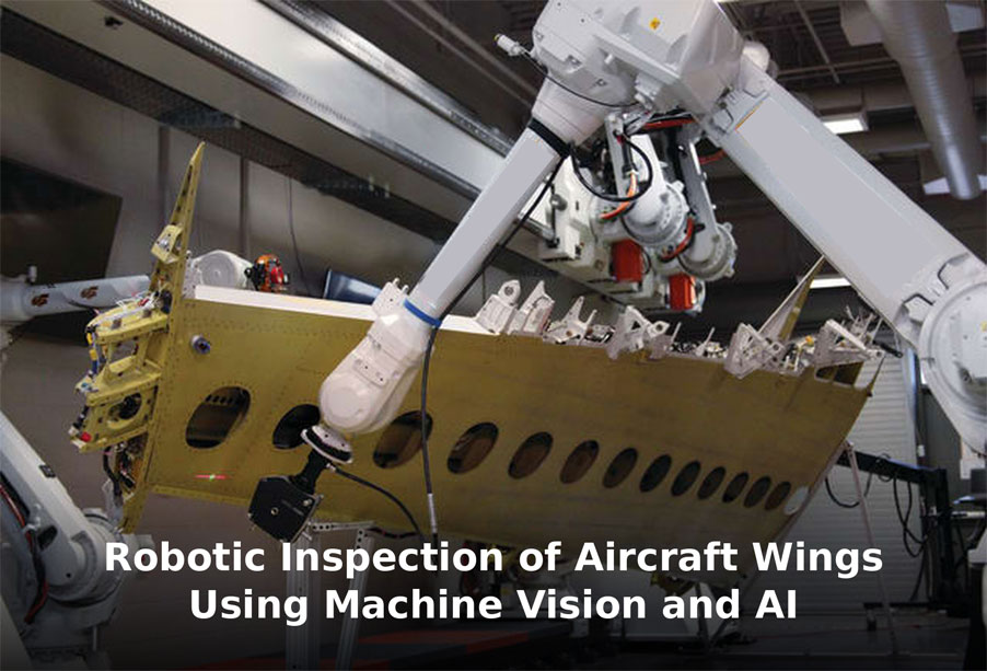
Robotic Inspection of Aircraft Wings Using Machine Vision and AI
Aircraft wings are large, geometrically complex structures containing skins, panels, fasteners, joints, sealants, coatings, access openings, and other critical features. Their dimensions and construction can also vary significantly between aircraft models.
Inspecting these surfaces manually can be slow and difficult to standardize. Inspectors must cover large areas, maintain close attention across repetitive features, work around curved geometry, and distinguish actual defects from reflections, surface texture, sealant, and acceptable manufacturing variation.
Intelgic automates this process by combining industrial robots or collaborative robots, line-scan and area-scan cameras, specialized lighting, AI-based defect detection, and the Certainty inspection software platform. Depending on the component and production environment, aircraft wings can be inspected in two principal ways: multiple line-scan cameras capturing continuous images while the wing or wing component moves through an inspection station, or an area-scan camera mounted on a robot or cobot moving around a stationary wing to capture images at programmed inspection locations.
Certainty manages inspection recipes for different wing models and variants. When a component enters the station, the appropriate recipe can be loaded automatically. The system then controls camera settings, illumination, image-acquisition sequences, robot paths, AI models, inspection regions, and acceptance criteria.
Inspection results can be exchanged with the existing PLC and connected to manufacturing systems such as MES, ERP, SCADA, and quality-management software.
Why Aircraft-Wing Inspection Is Challenging
Aircraft-wing inspection involves more than taking a few photographs of a large surface. The system must capture sufficient detail across changing geometry while maintaining repeatable image quality.
Large inspection area
A complete wing or large wing panel can extend across a considerable area. Detecting small defects requires high spatial resolution, but capturing the entire surface at that resolution creates large images and substantial processing requirements.
Curved and changing geometry
Wing surfaces are not flat. Their curvature, taper, leading edge, trailing edge, access panels, fairings, control-surface interfaces, and structural transitions change the camera-to-surface relationship. The inspection system must maintain an appropriate viewing angle, working distance, focus, and lighting condition as the geometry changes.
Multiple wing models and variants
Different aircraft models can have different:
A fixed inspection sequence cannot efficiently accommodate every variant.
Reflective and coated surfaces
Bare aluminium, machined metal, primer, paint, composite material, and protective coatings respond differently to light. Reflections can hide scratches and dents or create false indications that resemble defects.
Small defects on large parts
The system may need to find a very small scratch, crack, coating defect, damaged fastener, or foreign object on a surface several metres long. Camera resolution, field of view, lens selection, motion stability, lighting, and image overlap must all support the minimum defect size.
Restricted or hidden regions
Some areas are difficult to inspect from a single direction. Leading and trailing edges, curved transitions, recessed features, and lower surfaces may require additional camera positions or part movement.
Defects That Can Be Detected on Aircraft-Wing Surfaces
The detectable defect set depends on the sensor, optical resolution, viewing angle, lighting, surface preparation, and approved inspection requirements. A robotic machine-vision system can be configured to inspect for visible conditions such as:
Scratches and scoring
The system can identify linear surface damage and estimate its position, length, width, and orientation. Depth cannot normally be determined reliably from a single conventional 2D image. A 3D sensor or another approved measurement method may be required when depth is part of the acceptance criterion.
Dents and surface deformation
Dents may produce visible shading, distorted reflections, or altered surface contours. Multi-angle lighting can make shallow deformation easier to see. When quantitative depth or shape measurement is required, the system can incorporate 3D laser profiling or structured-light sensing.
Visible cracks
High-resolution cameras with controlled low-angle illumination can detect certain surface-breaking cracks. Detectability depends on crack opening, orientation, surface condition, paint, contamination, and image resolution. Fine, closed, painted-over, or subsurface cracks may require an approved nondestructive inspection method.
Corrosion indicators
Machine vision can detect visible corrosion products, discoloration, coating blisters, pitting, staining, and lifted surfaces. FAA corrosion guidance identifies conditions such as chipped or lifted paint, surface bulging, popped fasteners, cracks, and corrosion products as visually detectable indicators. It also emphasizes appropriate cleaning and detailed inspection of suspected areas. FAA AC 43-4B provides broader guidance on aircraft corrosion inspection and control.
Missing or damaged fasteners
AI can verify the presence and visible condition of rivets, bolts, screws, and other fasteners. Possible inspection criteria include:
Coating and paint defects
The inspection system may identify:
Sealant defects
Visible sealant conditions may include:
Joint and panel abnormalities
The system can inspect visible joints for:
Foreign-object debris
Tools, loose hardware, tape, protective material, swarf, fibers, and other unexpected objects may be detected when they appear within the inspected area.
Marking and identification errors
The same imaging system can verify labels, part markings, printed codes, warning symbols, orientation markings, serial numbers, and data-matrix codes.
Two Main Architectures for Automated Wing Inspection — 1. Multi-Camera Line-Scan Inspection
Intelgic can configure the inspection system around the component size, required defect resolution, production flow, geometry, and available cycle time.
Line-scan cameras capture an image one line at a time. As the wing, panel, skin, or other component moves relative to the cameras, consecutive lines are combined to create a continuous high-resolution image. Multiple line-scan cameras can be positioned across the inspection station to cover a wide surface.
How the line-scan system works
Why encoder synchronization matters
Line-scan imaging depends on controlled relative movement between the camera and the surface. If image capture is not synchronized with motion, the reconstructed image can become stretched, compressed, or distorted. Encoder-based triggering links each captured line to a known movement increment. The motion system must also limit vibration and speed variation that could reduce image sharpness.
Advantages of line-scan inspection
Limitations of line-scan inspection
Suitable applications
Multi-camera line-scan inspection can be effective for wing skins, flat or gently curved panels, sheet components, long structural elements, composite surface panels, and parts transported through a controlled production station.
For a complete wing, the transport system and camera arrangement must account for the structure's dimensions, support points, permissible handling, and geometric variation.
2. Robot- or Cobot-Mounted Area-Scan Inspection
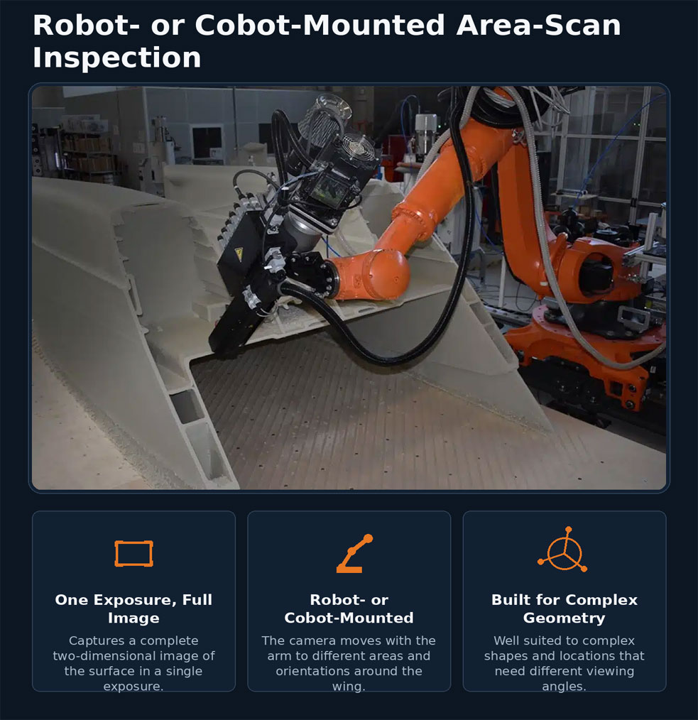
An area-scan camera captures a complete two-dimensional image in one exposure. Mounted on an industrial robot or cobot, it can be moved to different areas and orientations around the wing. This approach is well suited to complex geometries and inspection locations requiring different viewing angles.
How robotic area-scan inspection works
Advantages of robotic area-scan inspection
Intelgic uses this type of robotic positioning for complex parts where fixed cameras cannot provide complete surface coverage. Its robotic inspection architecture combines multi-axis motion, intelligent imaging, defect analysis, reporting, and optional PLC, ERP, and MES integration.
Limitations of robotic area-scan inspection
Extending coverage for large wings
For very large components, Intelgic can use a long-reach industrial robot, a robot installed on a linear track, multiple coordinated robots, a mobile robotic platform, a positioner that rotates or indexes the component, separate inspection zones, or a hybrid line-scan and area-scan configuration.
Line-Scan vs. Robotic Area-Scan Inspection
Neither architecture is universally superior. The right solution depends on the wing's geometry, production movement, required coverage, defect size, and available inspection time.
| Design factor | Multi-camera line scan | Robot-mounted area scan |
|---|---|---|
| Imaging method | Continuous lines during movement | Individual images at programmed poses |
| Best suited to | Long, accessible surfaces | Curved and complex geometry |
| Part movement | Normally required | Part may remain stationary |
| Camera movement | Usually fixed | Robot moves camera and lighting |
| Resolution | Very high across long surfaces | Configurable by camera position and field of view |
| Geometry flexibility | Moderate | High |
| Cycle-time behavior | Continuous, potentially high throughput | Depends on number of robot positions |
| Hidden-area access | Limited by camera arrangement | Better with multi-axis positioning |
| Variant handling | Recipe and camera-zone changes | Recipe-based robot paths and imaging settings |
| Typical complexity | Camera synchronization and data stitching | Robot path, calibration, and collision management |
Hybrid Wing-Inspection Systems
Some applications benefit from combining line-scan and area-scan cameras. A hybrid system may use:
This approach allows each sensor to perform the inspection for which it is best suited. The Certainty platform can coordinate the results and create one unified inspection record for the wing.
How Certainty Manages Wing Variants
Aircraft-wing dimensions, contours, feature locations, and inspection requirements vary between models. Certainty addresses this variation through model-specific inspection recipes. A recipe can contain:
Automatic recipe loading
The inspection recipe can be selected automatically using a barcode, data-matrix code, RFID, MES work order, PLC production signal, part-recognition camera, or operator selection with verification. Automatic loading reduces manual setup and helps prevent inspection using the wrong wing configuration.
Geometry-based image acquisition
Certainty can adjust imaging according to the local wing geometry. For example, a flat surface may use coaxial or diffuse lighting, a scratch-sensitive area may use low-angle illumination, a curved section may require a revised robot angle and focus distance, a reflective location may use polarization, a critical fastener region may use a smaller field of view and higher resolution, and a dent-inspection zone may trigger a 3D sensor.
Part Localization and Coordinate Alignment
The physical wing may not arrive in exactly the same position for every inspection. Variation may result from:
Reference cameras, laser sensors, or 3D imaging can detect known features and calculate the wing's actual position. The inspection system can then transform the stored inspection coordinates into corrected camera or robot positions.
For large structures, local reference features may be used in addition to one global coordinate system. This helps compensate for small differences between the digital model and the actual manufactured component.
Camera, Lens, and Lighting Selection
The imaging hardware must be selected from the inspection requirement — not simply from the overall size of the wing. Important parameters include:
Lighting options
Possible lighting techniques include:
The most effective lighting arrangement often changes between inspection zones. Certainty can trigger the appropriate lights as part of each imaging recipe.
How AI Analyzes Wing Images
Captured images are processed by Intelgic's AI models and inspection algorithms. The software may perform:
Defect detection
The system identifies and classifies visible scratches, dents, coating anomalies, corrosion indicators, damaged fasteners, sealant defects, and other trained conditions.
Anomaly detection
Anomaly models can flag regions that differ from validated examples of acceptable surfaces, including unexpected defects that do not fit a predefined category.
Segmentation
The AI outlines the defect at pixel level, allowing the system to estimate its visible area, length, width, and location.
Feature verification
The software checks that fasteners, access covers, labels, sealant paths, and other expected features are present in the correct locations.
Image-quality verification
Before making a quality decision, the system can check whether the image is in focus, correctly exposed, free from excessive glare, properly aligned, unobstructed, and captured at the required resolution. An invalid image should trigger reacquisition or a review result rather than an automatic pass.
Defect Mapping and Digital Traceability
Each detected condition can be mapped to a location on the wing. A digital inspection record may include:
An operator can select a defect on the wing map and open the corresponding image. This makes it easier to locate the physical defect, conduct secondary inspection, manage rework, and retain evidence for quality audits.
PLC and Manufacturing-System Integration
Intelgic's wing-inspection system can be integrated with existing factory automation and manufacturing software.
PLC integration
The inspection system can exchange signals with the PLC for part arrival, part identity, conveyor readiness, inspection start, recipe confirmation, camera triggering, robot status, inspection completion, pass or fail result, reject or rework routing, and fault and alarm status.
MES integration
Integration with the manufacturing execution system can support work-order retrieval, automatic recipe selection, part genealogy, serial-number tracking, inspection-result storage, rework workflows, production dashboards, quality trend analysis, and audit records.
Other system connections
Depending on the factory architecture, Certainty can also connect with ERP systems, SCADA platforms, quality-management systems, manufacturing databases, cloud dashboards, data historians, and maintenance systems.
Intelgic's existing complex-part inspection systems support PLC and ERP/MES connectivity, annotated inspection records, timestamps, and digital reporting. Intelgic's system overview describes this broader integration approach.
Visual Inspection and NDT Have Different Roles
Robotic machine vision is effective for conditions visible on the wing surface. It does not directly inspect every internal or subsurface condition. Surface imaging cannot by itself confirm:
These characteristics may require approved nondestructive inspection technologies such as ultrasound, eddy current, thermography, shearography, radiography, or other methods specified by the manufacturer.
The FAA describes visual inspection as a method for assessing structural condition, detecting manufacturing errors, and identifying visible cracks, corrosion, disbonding indications, wear, and accidental damage. FAA AC 43-204 also makes clear that visual inspection is one part of a broader aircraft-inspection program.
Intelgic's automated vision system should therefore be configured around defined visual and dimensional inspection objectives. Applicable OEM instructions, engineering specifications, approved NDT procedures, and regulatory requirements govern final acceptance.
Benefits of Robotic Aircraft-Wing Inspection
Consistent surface coverage
The system follows a defined imaging plan and checks every programmed region.
Adaptability across wing models
Certainty recipes allow one system to inspect multiple variants using different camera settings, robot paths, AI models, and quality criteria.
High-resolution inspection of large surfaces
Line-scan cameras can produce detailed continuous images, while robot-mounted area-scan cameras can capture close-up views of critical locations.
Better access to complex geometry
Robotic motion allows cameras and lights to be oriented around curves, edges, joints, and recessed areas.
Reduced inspection subjectivity
AI and measurement algorithms evaluate each image using repeatable criteria.
Faster defect localization
A digital wing map identifies the position of every flagged defect for secondary inspection or rework.
Production traceability
Images, defect data, recipe versions, and inspection results can be linked to each wing or component.
Earlier process feedback
Defect trends can help identify problems in forming, drilling, riveting, fastening, sealing, coating, handling, and assembly operations.
Important Design Considerations
Required defect resolution
The smallest defect determines the necessary optical resolution. A system intended to find broad coating damage will differ from one designed to detect fine cracks or fastener-head damage.
Inspection cycle time
The required production rate determines how many cameras, robots, and processing units may be needed.
Wing handling
The system must support the component without introducing deformation or damage. Conveyor and fixture design must follow approved handling requirements.
Robot coverage
Large wings may require a robot track, several inspection stations, or multiple robots.
Image volume
High-resolution line-scan and area-scan systems can generate substantial amounts of data. Storage rules should specify which images are retained and for how long.
Calibration
Camera geometry, robot coordinates, lighting, line-scan synchronization, and 3D measurements require periodic verification.
False rejects and missed defects
The system should be validated separately for each defect category, wing variant, material, and surface condition.
System availability
If inspection is inline, the production plan should define what happens during camera, robot, network, or software downtime.
Implementing an Automated Wing-Inspection System
A structured implementation process may include:
Intelgic's Robotic Aircraft-Wing Inspection Solution
Intelgic designs complete automated inspection systems for large and geometrically complex aerospace components. A wing-inspection system can combine:
Intelgic selects the architecture according to the wing size, geometry, surface materials, defect requirements, production flow, inspection time, and available factory space.
For long surfaces moving predictably through production, multiple synchronized line-scan cameras can provide continuous high-resolution imaging. For curved surfaces and features requiring different viewing angles, a robot- or cobot-mounted area-scan camera can move to the required inspection positions.
When both requirements exist, Intelgic can develop a hybrid system managed through Certainty.
Conclusion
Robotic aircraft-wing inspection enables manufacturers to examine large and complex surfaces with greater consistency, traceability, and flexibility.
Multiple line-scan cameras can continuously image wings or wing components as they move through a controlled conveyor or transfer system. Robot- or cobot-mounted area-scan cameras can inspect curved surfaces, fastener locations, joints, recessed areas, and other features from optimized angles.
Certainty allows model-specific inspection recipes to be created for different wing variants. The correct recipe can be loaded automatically and used to control imaging settings, illumination, robot paths, AI models, inspection zones, and reporting requirements.
By integrating the inspection cell with the existing PLC, MES, and other manufacturing systems, Intelgic can connect defect detection directly with production control, traceability, rework, and quality analytics. Looking to automate aircraft-wing inspection? Contact Intelgic to discuss a line-scan, robotic area-scan, or hybrid AI inspection system powered by the Certainty platform.
Frequently Asked Questions
How can aircraft wings be inspected automatically? +
Aircraft wings can be inspected using multiple line-scan cameras while the component moves through an inspection station, or with area-scan cameras mounted on robots or cobots. Hybrid systems can combine both methods.
When should line-scan cameras be used? +
Line-scan cameras are suitable for continuously imaging long, accessible surfaces while the component moves at a controlled speed. They can provide high resolution over large areas.
When is a robot-mounted area-scan camera better? +
Robotic area-scan inspection is appropriate for curved surfaces, complex geometry, recessed features, multiple viewing angles, and components that remain stationary during inspection.
Can one system inspect different wing models? +
Yes. Certainty can store a separate inspection recipe for each model or variant. The correct recipe can be loaded automatically using the part ID, MES work order, barcode, data-matrix code, RFID, or PLC signal.
What does an inspection recipe control? +
A recipe may control the robot path, active cameras, imaging positions, exposure, focus, lighting, conveyor synchronization, AI models, inspection regions, acceptance thresholds, and reporting rules.
What defects can AI machine vision detect on wings? +
Depending on the validated application, AI can identify scratches, visible cracks, dents, coating defects, corrosion indicators, missing or damaged fasteners, sealant anomalies, surface contamination, assembly errors, and foreign objects.
Can the system detect internal wing defects? +
Optical machine vision primarily detects visible or optically measurable surface conditions. Internal defects require appropriate approved NDT methods, which may include ultrasound, eddy current, thermography, shearography, or radiography.
Can the inspection system connect to an existing PLC? +
Yes. The system can exchange part, recipe, status, trigger, result, alarm, and routing signals with the existing PLC.
Can inspection data be transferred to an MES? +
Yes. Results, defect locations, images, serial numbers, timestamps, and recipe information can be integrated with an MES or another manufacturing and quality system.