How Robot Payload, Reach, and Cycle Time Affect Palletizer Design
Selecting a robot for a palletizing application involves much more than checking how much weight it can lift. A robot may have sufficient payload capacity but lack the reach required to access every pallet position. Another robot may offer excellent reach but be unable to complete the required number of cycles per minute. A technically capable robot may also perform poorly if the end-of-arm tool, product infeed, pallet exchange, and safety system are not designed as one coordinated cell.
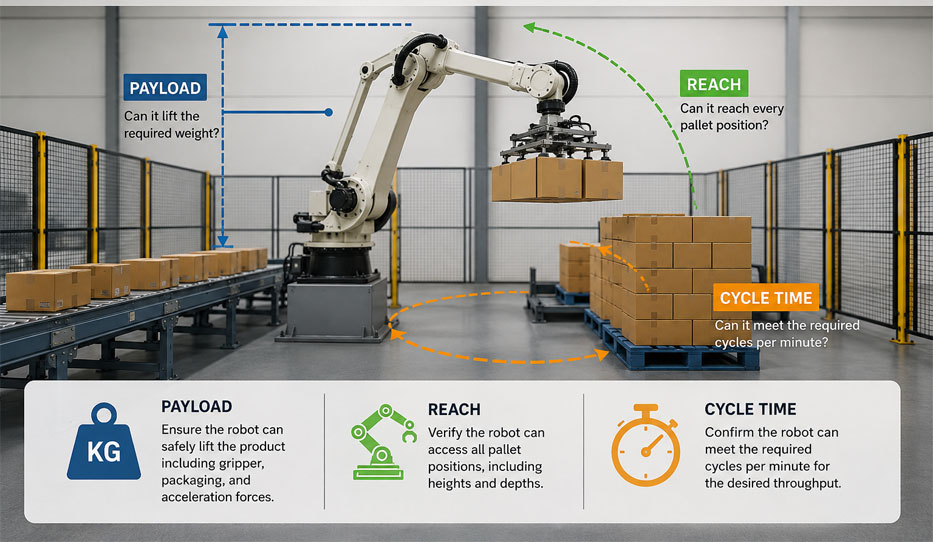
Three factors have a particularly strong influence on palletizer design: robot payload, robot reach, and required cycle time. These parameters are closely connected. Increasing the payload can reduce available speed. Extending the robot farther from its base can affect allowable loads and motion performance. Reducing cycle time may require multi-product picking, which increases both payload and end-of-arm tooling complexity.
This guide explains how payload, reach, and cycle time affect robotic palletizing system design—and what manufacturers should evaluate before choosing a robot.
Understanding the Three Core Palletizer Design Parameters
Robot payload
Robot payload is the maximum load that the robot is designed to carry at its wrist under specified operating conditions.
The payload is not simply the weight of the product. It normally includes:
The robot must safely handle the complete moving load throughout the programmed motion.
Robot reach
Robot reach describes how far the robot can extend from its base to a defined point at its wrist. It is normally expressed as a maximum horizontal reach.
Maximum reach alone does not define the robot's entire usable work area. Palletizer design must consider the robot's complete working envelope, including:
The robot must reach every pickup and placement point with the required tool orientation.
Cycle time
Cycle time is the amount of time required to complete one defined palletizing sequence.
For a single-product pick, a cycle may include:
Cycle time determines how many products the system can handle per minute or hour. It must match or exceed the production rate without causing products to accumulate at the end of the line.
How Robot Payload Affects Palletizer Design
The total moving load must be calculated
A common mistake is selecting a robot based only on the heaviest product.
Consider a system that needs to lift a 25 kg carton. If the gripper weighs 35 kg, the combined static load is already 60 kg. Sensors, brackets, valves, wiring, and other equipment add more weight.
If two cartons must be picked at the same time, the product load becomes 50 kg. The robot may then need to carry a total of 85 kg or more.
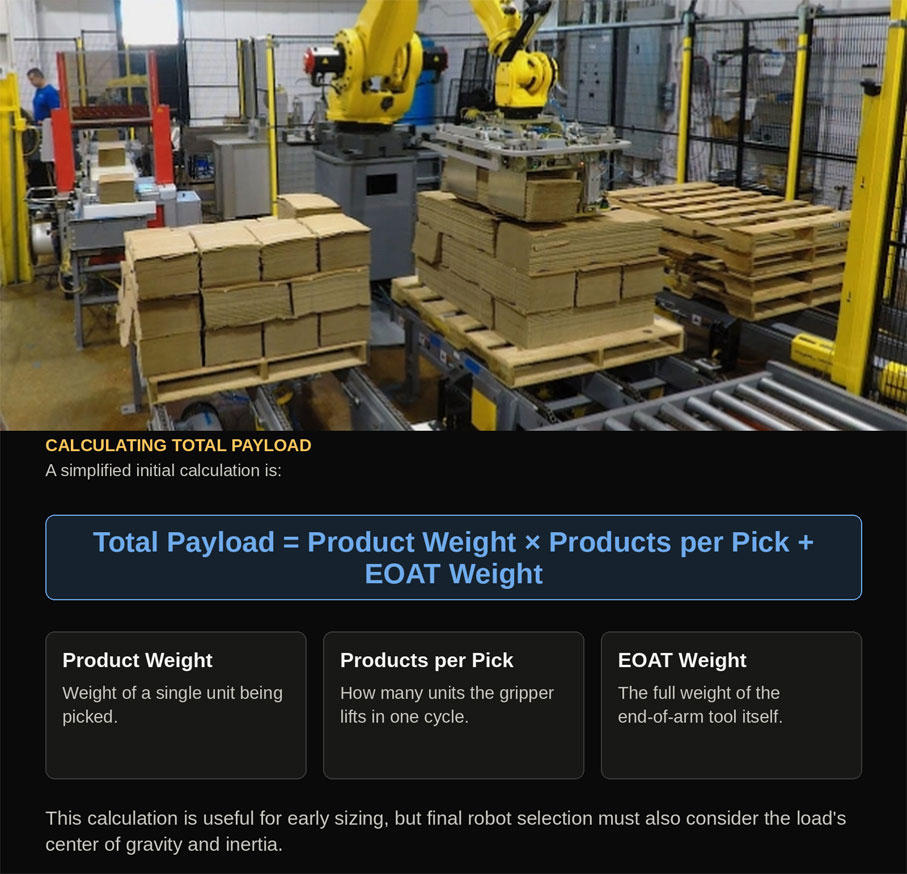
A simplified initial calculation is:
Total payload = Product weight × Number of products per pick + Complete EOAT weight
This calculation is useful for early sizing, but final robot selection must also consider the load's center of gravity and inertia.
The center of gravity matters
A robot's rated payload generally assumes that the load's center of gravity falls within specified limits.
A long or offset gripper may place the combined center of gravity far from the robot wrist. This creates additional torque on the robot's axes—even when the total weight is below the nominal payload rating.
The center of gravity can shift when:
Robot manufacturers provide load diagrams and wrist-load limits that must be checked during engineering.
Load inertia affects motion
Inertia describes a load's resistance to changes in movement. A wide, long, or offset load can produce high inertia even when it is relatively light.
High-inertia tooling may require reduced acceleration and slower rotational movement. This can increase cycle time and place additional stress on the robot. Engineers must evaluate:
Heavier grippers reduce usable product payload
End-of-arm tooling should be strong enough for the application but not unnecessarily heavy. A heavy tool can:
Lightweight engineering can improve palletizer performance, provided that stiffness, durability, and safety are not compromised.
Payload affects the robot base and supporting structure
Higher robot payloads create greater forces during acceleration, deceleration, and emergency stops. The robot pedestal, base plate, anchors, and factory floor must withstand these loads. A suitable foundation may require:
Installing a high-payload robot on an inadequate structure can affect accuracy, reliability, and safety.
A larger payload rating is not always better
Choosing the largest available robot may appear to provide flexibility, but unnecessary oversizing can increase equipment cost, cell footprint, power consumption, foundation requirements, safety distances, and maintenance costs. The objective is to select a robot with adequate capacity and an appropriate engineering margin—not simply the highest payload rating.
How Robot Reach Affects Palletizer Layout
Every pickup and placement point must be accessible
A palletizing robot may need to reach:
Designers must confirm reach at every required point and at every pallet layer. The bottom corner closest to the robot may be difficult to access because it falls inside the robot's minimum working radius. The far top corner may be difficult because it approaches maximum horizontal and vertical extension.
Maximum published reach is not always usable reach
A robot's maximum reach is measured at its wrist. The actual product pickup point may be located beyond the wrist because of the gripper's length.
Although a longer tool can extend the effective reach, it also changes the center of gravity and increases inertia. It may therefore reduce the allowable payload or motion speed. The robot should not be selected with its critical operating points positioned exactly at the boundary of its working envelope. A practical design includes clearance for product variation, pallet-position tolerances, tool deflection, robot path optimization, future product sizes, and maintenance access.
Pallet height affects vertical reach
The robot must place products from the bottom layer to the maximum finished pallet height. Low placements can be challenging if the robot is mounted too high. Top layers can become inaccessible if the robot is mounted too low. Possible solutions include:
Pedestal height should be determined through complete reach simulation rather than estimated from maximum pallet height alone.
Multiple pallet positions increase reach requirements
Many palletizing cells use two pallet positions so the robot can build one pallet while the completed pallet is removed from the other position. A single robot may also serve multiple production lines, different product infeed conveyors, three or more pallet destinations, and separate pallets for different SKUs. Every additional station expands the required work envelope and increases travel distance. A robot with sufficient nominal reach may still be too slow if it must repeatedly travel between widely separated points.
Robot placement affects cell footprint
Positioning the robot centrally can reduce travel distance and improve access to multiple pallets. However, the cell must also accommodate safety guarding, forklift or pallet-truck access, product conveyors, empty-pallet loading, finished-pallet removal, operator access, maintenance space, and control panels and utilities. The robot's location should balance reach, cycle time, safety, and material flow.
Reach must be verified with the actual tool
Reach simulations should use the complete end-of-arm tool and real product dimensions. A robot may reach a pallet coordinate with an empty wrist but be unable to place a large carton there without interference. Potential collision points include adjacent products, completed pallet layers, conveyor frames, pallet guides, safety fencing, robot pedestals, cell structures, and the robot's own arm.
How Cycle Time Affects Palletizer Performance
Production rate determines required capacity
If a production line delivers 20 cartons per minute and the robot picks one carton per cycle, the average robotic cycle must be completed in three seconds or less. A simplified relationship is:
Required cycle time in seconds = 60 ÷ Required picks per minute
However, products per minute and picks per minute are not always the same. If the robot picks two cartons in each cycle:
Required picks per minute = Products per minute ÷ Products per pick
For a line producing 20 cartons per minute with two cartons per pick, the robot needs approximately 10 pick cycles per minute, corresponding to an average six-second cycle. Multi-picking can reduce the required number of cycles, but it increases tool weight, payload, product-grouping requirements, and pattern-planning complexity.
Published robot speed does not equal application cycle time
Robot data sheets may provide axis speeds or performance under standardized conditions. Actual palletizing cycle time depends on:
The correct way to estimate performance is through application-specific simulation and, where necessary, physical testing.
Gripping time contributes to the cycle
The robot may need to pause while the gripper establishes and verifies a secure hold. For a vacuum tool, the sequence may include tool contact, vacuum generation, required vacuum-level confirmation, and product lifting. For a mechanical tool, it may include finger positioning, jaw closure, gripping-force application, and closed-position confirmation. Release time must also be considered. A fraction of a second added to every pick can have a significant effect over thousands of daily cycles.
Pallet pattern changes the travel path
Not every product position requires the same amount of time. A placement near the pickup conveyor may be completed quickly, while a position on the far side of the pallet may require a longer path. Upper layers may also require different approach and departure movements. The average cycle time should therefore be calculated across an entire pallet pattern—not from the fastest or most convenient placement.
Pallet changes create interruptions
Even when product-handling cycles meet the required rate, production can stop while a completed pallet is removed and an empty pallet is introduced. Pallet-change time can be reduced through dual pallet stations, automatic pallet dispensers, pallet conveyors, turntables, automated guided vehicles, autonomous mobile robots, accumulation conveyors, and product buffering. The complete system throughput must include these non-picking activities.
Upstream and downstream equipment affect cycle time
A fast robot cannot compensate for poor product presentation. The cell may lose time if products arrive too close together, in inconsistent orientations, at irregular intervals, damaged or tilted, in the wrong sequence, or without enough accumulation capacity. Similarly, finished-pallet discharge, wrapping, labeling, and forklift collection must keep pace with pallet production.
How Payload, Reach, and Cycle Time Interact
These three parameters cannot be evaluated independently.
Increasing products per pick
Picking two or more products per cycle can increase throughput, but it also increases total payload, requires a larger gripper, moves the center of gravity, increases inertia, may reduce acceleration, requires product grouping, and changes pallet-placement access. The expected cycle-time improvement must be validated against the slower motion caused by the heavier load.
Increasing reach
A longer-reach robot can serve more pallet positions, but additional reach may require a larger robot, increase cell footprint, extend travel distances, reduce cycle performance, introduce more difficult wrist orientations, and increase structural loads. In some cases, two smaller palletizing cells may perform better than one large robot serving widely separated lines.
Increasing payload capacity
A higher-payload robot can handle larger tools and multi-picks, but it may be physically larger and require more space. If the application involves long movements, the larger robot does not automatically produce a shorter cycle.
Reducing cycle time
Attempts to shorten cycle time may require higher acceleration and more aggressive paths. These changes can increase product movement within packaging, vacuum or gripping-force requirements, robot and tooling loads, pallet-placement impact, wear on mechanical components, and the risk of unstable packages shifting. The fastest possible motion is not always the most reliable production motion.
A Practical Palletizer Sizing Example
Consider a production line with these requirements:
The initial payload calculation is:
Product payload = 18 kg × 2 = 36 kg
Total static payload = 36 kg + 30 kg = 66 kg
A robot rated for exactly 66 kg would not be an appropriate selection. The application still requires verification of the center of gravity, inertia, wrist torque, dynamic motion, and engineering margin.
With two cartons per pick, the system requires:
16 cartons per minute ÷ 2 cartons per pick = 8 cycles per minute
Average permitted cycle time = 60 ÷ 8 = 7.5 seconds per cycle
The next step is to simulate all positions across both pallets. If far-side placements take longer than 7.5 seconds, the design may require:
This example shows why payload, reach, and cycle time must be assessed together.
Design Margins and Future Requirements
A palletizer should not be designed to operate continuously at the absolute limit of every specification. Reasonable margins can help accommodate:
Excessive margins can lead to unnecessary oversizing, while inadequate margins can create reliability problems. The appropriate allowance should be based on engineering analysis and the application's expected future development.
Manufacturers should identify planned changes before the system is finalized, including:
Why Robot Simulation Is Important
Robotic simulation allows engineers to evaluate a palletizing concept before physical equipment is installed. A simulation can help verify:
Simulation results should be supported by gripper testing and accurate product data. A simulation based on incorrect package dimensions, weights, conveyor positions, or gripping delays will produce misleading results.
Common Palletizer Design Mistakes
Selecting the robot from product weight alone
The complete end-of-arm load, center of gravity, inertia, and dynamic forces must be considered.
Using maximum reach as the layout target
Operating at the boundary of the robot envelope can restrict tool orientation and leave insufficient tolerance for real-world variation.
Estimating cycle time from robot speed alone
Product arrival, gripping, pallet patterns, pallet exchange, and equipment synchronization all contribute to actual throughput.
Ignoring the slowest pallet position
The fastest pick-and-place movement does not represent the average or worst-case production cycle.
Designing without representative product samples
Actual packaging behavior can affect gripping time, robot acceleration, and achievable placement speed.
Failing to include pallet-change time
An otherwise fast system can become a production bottleneck if finished pallets cannot be removed quickly.
Choosing oversized equipment without analysis
A larger robot can increase cost and footprint without necessarily improving application performance.
Omitting future production requirements
A cell designed only around the current product may require major modifications when new formats or higher production rates are introduced.
How Trans Automation Designs Robotic Palletizing Systems
Trans Automation, Intelgic's robotic automation division, specializes in developing palletizing systems based on actual production requirements.
The engineering process may include:
Depending on the application, Trans Automation can integrate industrial robots or cobots, custom grippers, product conveyors, pallet dispensers, machine vision, slip-sheet systems, safety guarding, pallet conveyors, wrapping equipment, and factory-control interfaces.
Conclusion
Robot payload, reach, and cycle time are fundamental to palletizer design, but none should be considered in isolation. Payload calculations must include the product, end-of-arm tooling, center of gravity, and inertia. Reach analysis must confirm access to every pickup and placement position with the actual gripper and product. Cycle-time calculations must represent the entire operation, including gripping, robot travel, pallet patterns, pallet changes, and equipment synchronization. The most reliable palletizing systems are designed through careful data collection, engineering calculations, product testing, and robotic simulation. This approach helps manufacturers avoid undersized robots, excessive equipment costs, unreachable pallet positions, and production bottlenecks. Planning a robotic palletizing project? Contact Intelgic to discuss payload, reach, cycle-time, and system-design requirements with the robotic automation specialists at Trans Automation.
Frequently Asked Questions
What does robot payload mean in a palletizing application? +
Robot payload is the complete load carried at the robot wrist. It includes the product, end-of-arm tool, mounting hardware, sensors, valves, cables, and any other supported equipment.
Should I choose a robot whose payload matches the product weight? +
No. The gripper and all associated components must be included. The load's center of gravity, inertia, wrist torque, and dynamic motion must also be checked.
How much extra robot payload capacity is required? +
There is no universal percentage suitable for every application. The necessary margin depends on product variation, tool design, center of gravity, inertia, motion, future requirements, and the robot manufacturer's load limits.
Does a longer-reach robot reduce palletizing speed? +
It can. A longer-reach robot may be larger, and serving distant positions creates longer travel paths. Actual cycle performance should be verified through application-specific simulation.
How is palletizing cycle time calculated? +
Cycle time includes moving to the pickup point, gripping and confirming the product, travelling to the pallet, placing and releasing the product, and returning for the next pick. Pallet changes and other interruptions must also be included in overall throughput calculations.
Can multi-picking improve palletizing throughput? +
Yes. Picking several products per cycle reduces the required number of robot cycles. However, it also increases payload, tool size, inertia, and product-grouping complexity.
Why is robot simulation necessary? +
Simulation helps verify reach, tool orientation, collisions, cycle time, robot utilization, pedestal height, and the feasibility of the complete cell layout before equipment is installed.
Can one palletizing robot serve multiple production lines? +
Yes, provided its payload, reach, and cycle capacity are sufficient. Product arrival rates, travel distances, pallet locations, and the consequences of shared-cell downtime must also be evaluated.