Detecting Leaks and Surface Damage on Aircraft Fluid Lines
Aircraft fluid lines transport fuel, hydraulic fluid, lubricating oil, coolant, oxygen, pneumatic air, water, and other media throughout an aircraft. A relatively small tube, hose, fitting, or coupling can therefore perform a safety-critical function.
Fluid lines operate in demanding conditions. They may be exposed to pressure cycles, vibration, temperature changes, aggressive fluids, installation stresses, contamination, and contact with surrounding components. Over time, these conditions can cause leaks, cracks, chafing, corrosion, dents, damaged fittings, or other forms of deterioration.
Effective inspection must answer two different questions: is the fluid line leaking, and does the line have physical damage that could lead to a future failure? These questions often require different inspection technologies. A line can leak through a loose fitting while its tube surface remains undamaged. Conversely, a scratched, corroded, or partially crushed tube may not leak during inspection but could still be unserviceable.
This guide examines the defects found on aircraft fluid lines, the methods used to detect them, and how machine vision, AI, 3D sensing, pressure testing, and robotic automation can improve inspection consistency and traceability.
What Are Aircraft Fluid Lines?
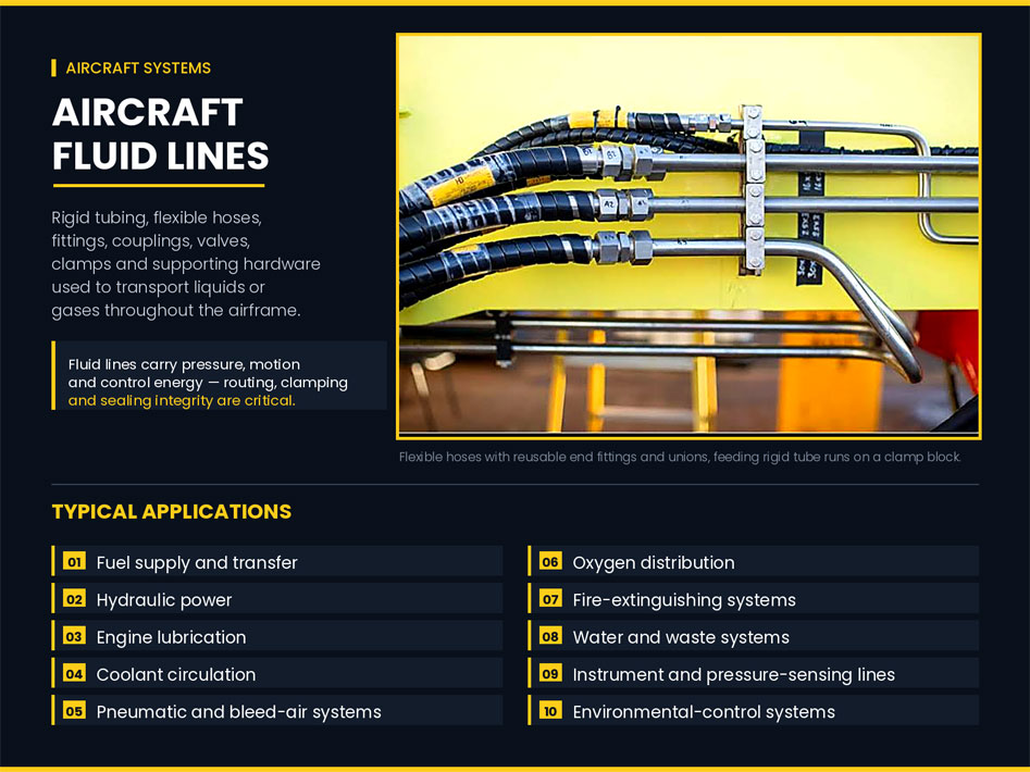
Aircraft fluid lines include rigid tubing, flexible hoses, fittings, couplings, valves, clamps, and supporting hardware used to transport liquids or gases.
Typical applications include:
Rigid aircraft tubing may be manufactured from aluminium alloys, stainless steel, titanium, copper alloys, or other approved materials. Flexible lines may contain synthetic inner tubes, reinforcement layers, protective covers, and specialized end fittings.
The material, wall thickness, operating pressure, temperature, fluid compatibility, installation environment, and criticality determine how each line must be manufactured, inspected, installed, and maintained.
Why Fluid-Line Inspection Is Important
A fluid-line failure can cause more than the loss of system pressure. Depending on the system, a leak can result in:
Surface damage can also act as a stress concentrator. Vibration and repeated pressure cycles may cause a small crack or defect to grow over time.
The FAA advises that hydraulic lines and fittings be inspected for leaks, loose anchorage, scratches, kinks, cracks, burrs, chafing, and other damage. Its guidance also states that evidence of fluid loss or leakage should be investigated. See FAA Advisory Circular AC 43.13-1B.
Aircraft and component manufacturers may impose more restrictive limits than general guidance. The applicable aircraft maintenance manual, component maintenance manual, engineering drawing, service bulletin, airworthiness directive, and approved maintenance data always take precedence.
Common Defects in Aircraft Tubes and Hoses

Fluid leakage
Leaks can occur at tube walls, hose covers or inner liners, flares, fittings, unions, seals, valves, manifolds, swaged connections, and brazed or welded joints. A visible wet area may identify the general region, but the source can be difficult to locate because fluid may travel along the line, a bracket, or an adjacent structure.
Scratches and scoring
Tools, clamps, fixtures, surrounding components, or handling equipment can scratch a tube surface. The acceptability of a scratch depends on its depth, location, direction, tube material, and approved damage limits.
Chafing
Chafing occurs when a fluid line repeatedly rubs against another line, clamp, cable, structure, or component. Vibration can gradually remove protective material and reduce wall thickness.
Dents and flattening
Impact, improper clamping, poor handling, or incorrect bending can deform a tube. Dents near bends may be especially significant because the material is already subjected to forming stress and altered geometry.
Kinks and wrinkles
Incorrect bending can locally restrict the flow area, distort the tube, and create stress concentrations.
Cracks
Cracks may form because of fatigue, vibration, manufacturing defects, improper forming, corrosion, excessive tightening, or installation stress. Areas around flares, bends, clamps, and fittings require particular attention.
Corrosion and pitting
Moisture, dissimilar-metal contact, chemical exposure, and damaged protective finishes can produce surface corrosion. Localized pitting may reduce the effective wall thickness.
Damaged flares and fittings
Incorrectly formed flares, burrs, cracks, misalignment, damaged threads, or excessive tightening can prevent proper sealing and increase stress.
Flexible-hose deterioration
Flexible hoses may experience cracking, hardening, softening, blistering, abrasion, bulging, delamination, cold flow, kinking, twisting, damaged reinforcement, fitting separation, or fluid seepage. Hose condition cannot always be determined from external appearance alone.
Incorrect installation
Even an undamaged line can become unreliable when it is forced into alignment, improperly supported, installed with insufficient clearance, twisted, bent below its approved minimum radius, clamped too tightly, allowed to contact another component, connected using an incorrect fitting, or exposed to excessive movement.
Leak Detection vs. Surface-Damage Inspection
Leak detection and surface inspection are related but should not be confused. A complete quality strategy may combine several of these methods.
| Inspection objective | What it identifies | Typical methods |
|---|---|---|
| Active leak detection | Fluid or gas escaping during a test or operation | Visual inspection, pressure decay, bubble testing, tracer gas, flow measurement |
| Leak-source localization | Exact point from which media escapes | Cameras, UV imaging, acoustic sensing, tracer-gas probes |
| Surface-damage inspection | Scratches, dents, corrosion, cracks and chafing | Machine vision, 3D profilometry, eddy current, penetrant inspection |
| Wall-thickness assessment | Internal or external material loss | Ultrasonic thickness measurement |
| Dimensional inspection | Diameter, ovality, bend geometry and deformation | Laser scanning, structured light, gauges |
| Installation inspection | Routing, clearance, clamp position and connection | 2D/3D vision and dimensional comparison |
Visual Inspection of Fluid Lines
Visual inspection is normally the first stage of fluid-line assessment. Inspectors look for:
Good visual inspection depends on access, lighting, surface cleanliness, viewing angle, inspector experience, and clearly defined acceptance criteria.
A dark stain does not always identify an active leak. It may be old residue or contamination from another source. Similarly, a very small clear-fluid leak may be difficult to see. Cleaning and controlled retesting may be necessary to distinguish a current leak from historical evidence, provided the procedure is permitted by the applicable maintenance instructions.
Pressure and Vacuum Leak Testing
Pressure testing determines whether a closed line or assembly can maintain a specified pressure over time. The component may be filled with an approved liquid or gas and stabilized at a defined pressure. The system then measures pressure loss, flow required to maintain pressure, escaping test media, visible bubble formation, and leakage at specific joints.
Vacuum-decay testing follows a similar principle but evaluates whether a component can hold a vacuum.
Test parameters must be controlled, including:
Temperature is particularly important. A change in temperature can change pressure even when no leak is present, producing an incorrect result.
Only approved test pressures, media, connections, and safety precautions should be used. Excessive pressure or incompatible test fluids can damage an aircraft component or create a hazardous condition.
Bubble Leak Testing
In a bubble test, an approved leak-detection fluid is applied to the pressurized area. Escaping gas produces visible bubbles. This method is simple and useful for locating leaks at fittings, joints, and accessible surfaces.
Its limitations include:
Automated imaging can improve bubble detection by monitoring bubble growth, position, and persistence under controlled lighting.
Tracer-Gas Leak Detection
Tracer-gas methods introduce a detectable gas — commonly helium — into a component or test chamber. A sensor measures gas escaping through a leak. Tracer-gas testing can detect much smaller leaks than ordinary visual or bubble methods.
Common configurations include:
Advantages include high sensitivity and quantitative leak-rate measurement. However, equipment cost, test-fixture design, background-gas control, component cleaning, and cycle time must be considered.
The selected test method and acceptance threshold must come from the applicable engineering and quality requirements.
Fluorescent Leak Detection
An approved fluorescent tracer may be added to a compatible fluid. Escaping fluid becomes more visible under ultraviolet or specialized illumination. Machine-vision cameras can detect fluorescence and distinguish it from the surrounding surface.
This approach may help locate small leaks in visually complex assemblies, but it must never be introduced without authorization. The tracer must be approved for the specific fluid system, materials, seals, aircraft, and maintenance procedure.
Unapproved dyes or additives can contaminate the system or affect fluid and component performance.
Acoustic and Ultrasonic Leak Detection
A pressurized gas escaping through a small opening generates high-frequency sound. Ultrasonic leak detectors convert this energy into a signal that can be measured and localized.
Acoustic methods can be useful where the escaping medium is not visible, the leak is too small to hear directly, a gas line is tested under pressure, or the component is difficult to coat with bubble solution.
Background noise, airflow, reflected sound, distance, and sensor orientation can influence results. Robotic positioning can improve repeatability by maintaining a controlled path and distance between the detector and the line.
Machine Vision for Surface-Damage Inspection
Machine vision uses industrial cameras, optics, lighting, and image-processing software to inspect the external condition of tubes, hoses, and fittings. A vision system can detect:
Why controlled lighting matters
Aircraft fluid lines can be reflective, curved, textured, or dark. Standard overhead lighting may create glare that hides defects or produces false indications. Inspection systems may use diffuse dome lighting, dark-field illumination, directional lighting, polarized lighting, multispectral illumination, ultraviolet lighting, or multiple images from different directions.
The camera and lighting arrangement should be tested using actual materials, finishes, defects, and contamination conditions.
AI-Based Defect Detection
Rule-based machine vision works well when defects can be described using consistent measurements such as width, length, contrast, position, or color. AI-based vision can be valuable when acceptable surfaces and defects have more complex natural variation.
AI may help classify:
An AI system requires representative training and validation data. Images should cover different tube materials, surface finishes, lighting variation, multiple defect severities, acceptable cosmetic variation, fluid types, part orientations, and production and maintenance environments.
AI does not determine airworthiness on its own. It provides an inspection result within a validated system governed by approved criteria and quality procedures.
3D Inspection of Dents and Deformation
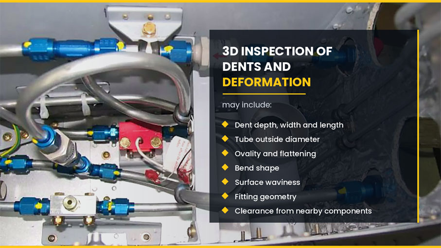
A two-dimensional image may show that a dent exists but may not accurately measure its depth. A 3D laser profiler, structured-light sensor, or other optical metrology system can capture the surface geometry of the line.
Measurements may include:
The measured values can be compared with engineering drawings, digital reference models, or approved inspection limits.
Reflective metal surfaces and cylindrical geometry require careful sensor selection and calibration. Multiple scans may be necessary to measure the complete circumference.
Detecting Cracks and Material Loss
Cameras can detect some open surface cracks, but small or tightly closed cracks may require a non-destructive testing method. Depending on the material and approved procedure, options may include:
Liquid penetrant inspection
Penetrant inspection can reveal surface-breaking discontinuities in nonporous materials. Correct cleaning, dwell time, developer application, interpretation, and post-cleaning are essential.
Eddy-current inspection
Eddy-current testing can detect surface and near-surface discontinuities in electrically conductive materials. It can also support material sorting and some thickness assessments. Probe design, frequency, lift-off, conductivity, curvature, coating thickness, and defect orientation influence performance.
Ultrasonic thickness measurement
Ultrasonic testing can measure remaining wall thickness and help identify thinning caused by wear or corrosion. Small-diameter tubing, curved surfaces, thin walls, coatings, and limited probe access can make measurement challenging. Specialized probes and calibrated reference standards may be required.
The inspection must follow an approved procedure and be performed or interpreted by appropriately qualified personnel where required.
Robotic Inspection of Aircraft Fluid Lines
Aircraft tubes often contain bends, branches, fittings, and surfaces that cannot be captured from one fixed camera position. A robotic inspection system moves one or more sensors around the component. It may inspect the line before installation, examine a fluid-line assembly, or evaluate accessible areas within a larger aircraft structure.
A robotic cell may include:
Typical robotic inspection sequence
Inspection During Manufacturing and Maintenance
Incoming material inspection
Material identity, tube dimensions, surface condition, and certification data can be verified before fabrication.
Post-forming inspection
After bending and flaring, the system can check bend angles, bend radii, tube profile, flattening, wrinkles, flare geometry, surface damage, and end orientation.
Post-assembly inspection
After fittings and hoses are assembled, the system can verify correct components, connection position, torque witness marks, clamp installation, routing, fitting orientation, and the absence of foreign objects.
Final leak and pressure testing
Automated equipment can pressurize the completed assembly, measure leakage, and record the test curve. A combined station can inspect dimensions, surfaces, assembly completeness, markings, and leak performance while maintaining part-level traceability.
Inspection during aircraft maintenance
Inspection on an installed aircraft presents additional challenges: restricted access, complex backgrounds, contamination, multiple line types, limited sensor clearance, variable aircraft condition, and maintenance time constraints.
Portable vision systems, borescopes, handheld 3D scanners, UV inspection devices, and compact robotic platforms may help document accessible areas. However, inspection automation used during maintenance must fit within the approved maintenance program. The aircraft maintenance manual and other approved data determine access, preparation, inspection technique, acceptance limits, and return-to-service actions.
FAA AC 43.13-1B remains active guidance, but the FAA states that it applies when manufacturer instructions are unavailable and when its methods are appropriate, directly applicable, and not contrary to manufacturer data. FAA's document information page explains this scope.
Advantages of Automated Inspection
Greater consistency
Robots and controlled sensors apply the same inspection path, lighting, distance, angle, and measurement logic to each component.
Better coverage
A robot can capture multiple views of curved tubing, fittings, bends, and assemblies that are difficult to evaluate with a fixed camera.
Quantitative measurements
3D sensors and test instruments convert subjective conditions into measurable results such as dent depth, diameter, clearance, pressure loss, or leak rate.
Digital traceability
The system can store part number, serial number, inspection date, recipe version, operator, images, 3D scans, leak-test curves, defect locations, and acceptance results. Inspection trends may identify deteriorating bending tools, worn fixtures, inconsistent flaring, poor handling, damaged packaging, or assembly problems before they affect a larger batch.
Reduced repetitive inspection
Automation can reduce the repetitive work involved in examining many similar parts while allowing qualified personnel to focus on borderline indications and root-cause analysis.
Challenges and Limitations
Hidden surfaces
A sensor cannot inspect a surface it cannot see or reach. Fixtures may need to rotate the component, or multiple sensors may be required.
Reflective materials
Polished stainless steel, aluminium, and titanium can produce glare and incomplete 3D data.
Cleanliness
Oil, water, sealant, dust, and fingerprints may resemble defects or hide them. Inspection must either control cleanliness or be trained and validated for realistic surface conditions.
Defect variability
Cracks, scratches, corrosion, stains, and leaks can vary widely in appearance. Representative samples are essential.
Very small acceptance limits
Detecting a defect is different from measuring it accurately. Resolution, calibration, uncertainty, and repeatability must be suitable for the acceptance limit.
Cycle time
Complete circumferential inspection of a complex tube can require many robot positions. The inspection strategy must balance coverage, resolution, and production throughput.
Regulatory and customer approval
An automated system cannot introduce its own acceptance criteria. Inspection methods and limits must align with approved engineering, regulatory, OEM, and customer requirements.
How to Validate an Automated Inspection System
Aerospace inspection systems require disciplined validation. The process should include:
The inspection system should fail safely when data is incomplete. A missed image, low-confidence AI result, unstable pressure reading, or failed calibration should generate an invalid or review-required result — not an automatic pass.
Questions to Ask Before Automating Fluid-Line Inspection
Manufacturers and maintenance organizations should define:
Aircraft Fluid-Line Inspection Solutions from Intelgic
Intelgic develops custom machine-vision, AI, 3D measurement, and robotic inspection systems for complex manufacturing applications. An automated aircraft fluid-line inspection solution may combine:
The system can be designed around the component geometry, defect types, inspection specifications, production rate, traceability requirements, and manufacturing environment.
Intelgic's role is to integrate the sensing, robotics, software, controls, and data infrastructure required for a dependable production inspection process. Final acceptance criteria and airworthiness decisions remain governed by the applicable approved engineering and maintenance requirements.
Conclusion
Detecting leaks and surface damage on aircraft fluid lines requires more than a single inspection method.
Visual and machine-vision systems can identify stains, chafing, scratches, corrosion, incorrect routing, and assembly problems. 3D sensors can measure dents, flattening, diameter, and bend geometry. Pressure-decay, bubble, fluorescent, acoustic, and tracer-gas methods can locate or quantify leaks. Eddy-current, penetrant, and ultrasonic methods can provide additional information about cracks and material loss.
The best inspection strategy starts with the failure mode and acceptance requirement. It then selects the sensing technology capable of measuring that condition with the necessary resolution, repeatability, and confidence.
Robotic automation can bring these technologies together, improve coverage, standardize sensor positioning, and create a digital inspection record for each component. Looking to automate inspection of aircraft tubes, hoses, fittings, or fluid-line assemblies? Contact Intelgic to discuss a custom robotic and AI-powered inspection system for your aerospace manufacturing process.
Frequently Asked Questions
What defects should be checked on aircraft fluid lines? +
Typical conditions include leakage, scratches, chafing, dents, flattening, kinks, cracks, corrosion, damaged flares, loose fittings, incorrect routing, inadequate clearance, and deteriorated hoses.
Can machine vision detect fluid leaks? +
Yes, when the leaking fluid or its residue is visually distinguishable. Controlled lighting, color imaging, UV fluorescence, and AI can improve detection. A pressure or tracer-gas test may still be required to quantify leakage.
Can a camera measure the depth of a dent? +
A conventional 2D camera generally cannot provide a dependable depth measurement by itself. A calibrated 3D laser or structured-light system is more appropriate for measuring dent geometry.
Can AI determine whether an aircraft tube is serviceable? +
AI can detect and classify defined visual conditions within a validated inspection system. Serviceability must be determined using the applicable OEM, engineering, regulatory, and maintenance criteria.
What is the most sensitive leak-detection method? +
Tracer-gas mass-spectrometer methods can detect very small leaks, but the appropriate method depends on the component, required leak limit, production rate, test environment, and approved procedure.
Can leak testing damage an aircraft fluid line? +
Incorrect test pressure, incompatible media, poor connections, or uncontrolled pressurization can damage a component. Testing must follow the approved pressure, medium, duration, and safety procedure.
Can automated inspection replace an aerospace inspector? +
Automation can perform repeatable measurements, identify defects, and record results. Qualified personnel may still be required to approve procedures, interpret specified indications, review uncertain cases, and make acceptance or return-to-service decisions.
Can Intelgic inspect both rigid tubes and flexible hoses? +
A system can be engineered for either type, but the inspection methods differ. Rigid tubes often require dimensional and surface inspection, while flexible hoses may require checks for abrasion, cracking, deformation, fitting condition, leakage, and assembly correctness.