AI Detection of Missing and Damaged Aircraft Rivets
Aircraft structures can contain thousands of rivets distributed across large, curved, and geometrically complex surfaces. Inspecting every required location manually is time-consuming and places considerable responsibility on inspectors, particularly when defects are small, surfaces are reflective, and components contain multiple contours or recessed areas.
Intelgic addresses this challenge with a robotic inspection system that combines robots or collaborative robots, industrial machine-vision cameras, controlled illumination, AI-based defect detection, and the Certainty inspection software platform.
The robot moves the imaging system across the component and positions the camera at every location where a rivet should be present. High-resolution images are captured using an imaging recipe optimized for that location. Intelgic's AI then analyzes the images to detect missing, damaged, incorrectly installed, or visually abnormal rivets.
The system can be engineered for small components or very large aerospace structures. Based on the component's size, shape, surface characteristics, and geometry, Certainty automatically applies the required imaging recipe, robot position, camera parameters, lighting conditions, and inspection criteria.
This article explains how AI-powered robotic rivet inspection works, the defects it can identify, and the factors aerospace manufacturers should consider when automating the process.
Why Aircraft Rivet Inspection Is Challenging
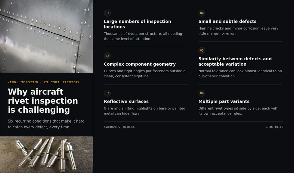
Aircraft rivets are often distributed over large areas and may be installed on flat, curved, angled, or recessed surfaces. A single component may contain different rivet types, sizes, orientations, and installation conditions. Several factors make inspection difficult.
Large numbers of inspection locations
Inspectors may need to verify hundreds or thousands of rivet positions on one assembly. Repetitive inspection increases the risk that a location will be overlooked.
Complex component geometry
Rivets may appear on curved fuselage panels, wing structures, frames, bulkheads, doors, access panels, fairings, and other three-dimensional assemblies. One fixed camera cannot normally view every location at the correct angle.
Reflective surfaces
Aluminium, titanium, coated metal, sealants, primers, and painted surfaces can create glare or shadows. A defect visible from one lighting direction may disappear from another.
Small and subtle defects
Fine cracks, edge damage, incorrect seating, surface marks, or slight deformation may be difficult to identify during a quick manual examination.
Similarity between defects and acceptable variation
Tool marks, sealant, coatings, surface texture, reflections, and normal rivet-to-rivet variation can resemble defects. An inspection system must distinguish true anomalies from acceptable appearance.
Multiple part variants
Different aircraft models or assembly variants may use different rivet patterns, specifications, and acceptance rules. The inspection system must load the correct configuration for each part.
Rivet Conditions That AI Vision Can Inspect
The exact inspection capability depends on image resolution, camera angle, illumination, rivet type, surface condition, and the availability of representative training samples. A robotic AI inspection system can be configured to identify visible conditions such as:
Missing rivets
The AI verifies whether a rivet is present at every required coordinate. It can also identify an empty hole or a location obscured by unexpected material.
Damaged rivet heads
Visible damage may include:
Incorrect rivet type
Where rivet types have visibly different head shapes, dimensions, colors, markings, or other features, the system can verify that the expected rivet has been installed.
Raised or improperly seated rivets
An incorrectly seated rivet may sit above the surrounding surface or display an abnormal edge profile. Depending on the required measurement accuracy, this condition may be inspected with multi-angle 2D imaging, photometric techniques, or a 3D sensor.
Excessive countersink or recessed condition
A countersunk rivet may sit too far below the surrounding surface. Precise depth verification generally requires calibrated 3D measurement rather than appearance-based classification alone.
Tilted rivets
A rivet head that is not aligned correctly with the surrounding surface may create an asymmetrical image or abnormal 3D profile.
Incorrect rivet-head shape or dimensions
The system can assess visible features such as:
Surface cracks around the rivet
Cracks may form around holes or fastener locations. Detectability depends on crack width, surface finish, orientation, lighting, camera resolution, and whether the crack is open at the surface.
Gaps and local deformation
The inspection may identify gaps around the rivet head, local panel deformation, pulled surfaces, or unusual contact between the rivet and the surrounding material.
Sealant-related anomalies
Where sealant is part of the assembly specification, the system may inspect for visible conditions such as:
Acceptance criteria must be defined by the applicable aerospace specification.
Foreign material and contamination
Unexpected debris, residue, loose material, or contamination near a rivet can be detected when it produces a visible difference from the approved surface condition.
How Intelgic's Robotic Rivet Inspection System Works
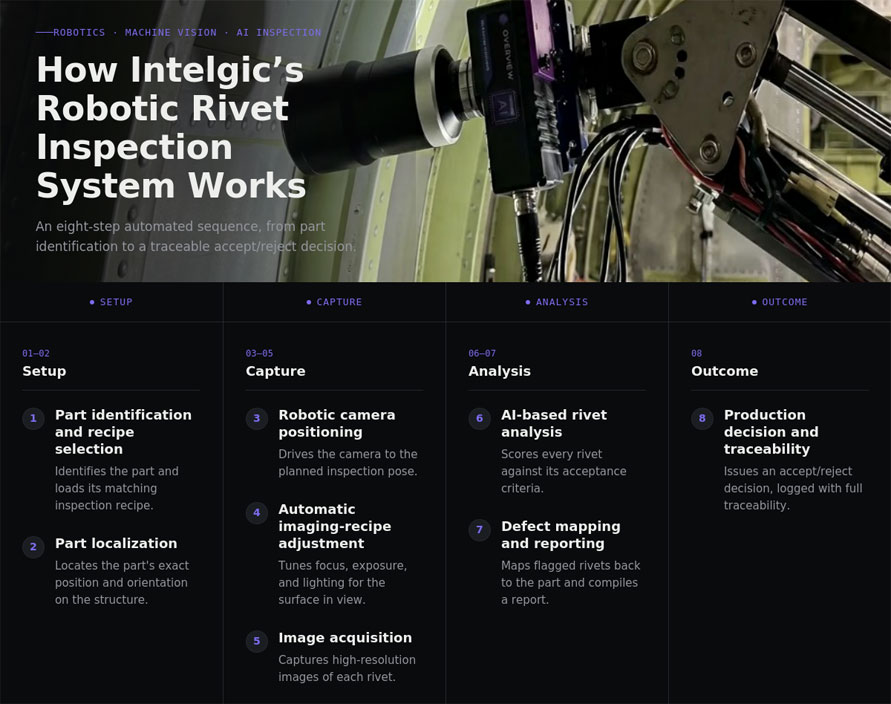
Intelgic's system integrates robotic motion, industrial imaging, AI analysis, and inspection-recipe management into one automated workflow.
1. Part identification and recipe selection
The system identifies the part using a barcode, data-matrix code, RFID tag, production-system signal, or operator selection. Certainty loads the correct inspection recipe for that part number or assembly variant. The recipe can define:
This prevents the system from evaluating a part using the wrong rivet map or acceptance criteria.
2. Part localization
The part may be placed in a fixture, presented on a conveyor, or positioned manually within the inspection cell. Cameras or 3D sensors identify reference features and establish the component's actual position. Certainty can use this information to align the inspection coordinate system with the physical part.
This step is important because even a small variation in part position can affect camera focus, lighting, and the location of the rivet within the image.
3. Robotic camera positioning
A robot or cobot moves the camera and lighting assembly across the component. At each inspection point, it positions the imaging system at a controlled distance, angle, orientation, focus position, field of view, and lighting direction.
For complex surfaces, the robot changes orientation so that the camera remains properly aligned with the local geometry. The robot can inspect locations that would be difficult to cover using fixed cameras alone. Intelgic uses this multi-axis approach in its broader robotic inspection systems for complex parts, where cameras and lighting are repositioned for different surfaces and viewing angles.
4. Automatic imaging-recipe adjustment
A single camera setup is rarely suitable for an entire aerospace component. A bright metallic rivet on a flat panel may require one exposure and lighting arrangement. A rivet in a recessed, curved, coated, or sealant-covered area may require another.
Based on the component geometry and inspection location, Certainty can automatically apply the required imaging recipe, including camera exposure, gain, focus, lighting intensity and direction, trigger timing, robot pose, sensor-to-surface distance, image preprocessing, the AI inspection model, and defect thresholds. This recipe-based approach enables one system to inspect components containing different surfaces, rivet types, and geometries.
5. Image acquisition
The industrial camera captures a high-resolution image of each rivet location. More than one image may be acquired when a defect is best revealed through different lighting directions or viewing angles. The system may use:
Camera, lens, lighting, and working distance are selected according to the minimum defect size that must be detected.
6. AI-based rivet analysis
The captured images are sent to Intelgic's AI defect-detection system integrated with Certainty. The AI evaluates the specified rivet location and determines whether the visible condition matches the approved quality criteria. Depending on the application, the software may perform rivet presence detection, rivet classification, surface-defect segmentation, anomaly detection, position measurement, head-shape analysis, comparison with an approved reference, defect-size estimation, and confidence scoring.
The system can classify each location as pass, fail, review required, or inspection invalid. An invalid result may be generated when an image is blurred, obstructed, incorrectly exposed, or captured from an unacceptable position.
7. Defect mapping and reporting
Every rivet result is linked to its physical location on the component. Certainty can create a digital defect map showing inspected rivet positions, missing rivets, damaged rivets, defect categories, measurement results, AI confidence, original and annotated inspection images, inspection time, and part and recipe information.
Quality personnel can select a flagged location and review the supporting image rather than searching manually across the entire component.
8. Production decision and traceability
After all required locations have been inspected, the system generates the overall part result. Inspection data can be associated with the part number, serial number, aircraft or assembly identifier, production batch, work order, inspection station, date and time, recipe version, AI-model version, operator, and individual rivet results.
The result can be shared with a PLC, manufacturing execution system, quality-management platform, or other factory system.
Inspection of Large Aircraft Components
Large aerospace structures create a coverage challenge because no single fixed camera can capture every rivet at the necessary resolution. Examples may include:
Intelgic can use a long-reach industrial robot, robot mounted on a linear track, mobile robotic platform, or coordinated multi-robot arrangement to cover the required inspection area.
Large-part design considerations
A large-component inspection system must account for:
Global robot repeatability alone may not be sufficient when the component position changes. Reference-feature detection can be used to correct the inspection path relative to the actual part.
Inspection of Small and Medium Components
For smaller components, a cobot or compact industrial robot can move the camera around the part. Alternatively, the robot may manipulate the component while the camera remains stationary. Typical parts may include:
Small-part systems may use fixtures, rotary tables, indexing stations, or conveyors to increase throughput. The most suitable arrangement depends on whether it is easier to move the imaging system or the component.
Why Controlled Lighting Is Critical
Rivet inspection is fundamentally an imaging problem before it becomes an AI problem. Reflective aircraft surfaces can create bright highlights, deep shadows, and changing appearances. A defect may become visible only when light strikes it from a particular direction.
Coaxial illumination
Light is directed along the camera axis. This can produce uniform images of relatively flat reflective surfaces.
Low-angle illumination
Light is directed almost parallel to the surface. Raised edges, scratches, cracks, and surface irregularities create strong contrast.
Dome lighting
Diffuse light surrounds the inspection area and reduces harsh reflections from curved or polished surfaces.
Multi-directional lighting
Images are captured while different lights are activated sequentially. The resulting image set helps reveal defects regardless of orientation.
Polarized illumination
Polarizers can reduce glare and improve contrast on reflective coatings and metallic surfaces.
Certainty can select and trigger the appropriate lighting arrangement for each rivet location.
When 3D Sensing Should Be Added
AI analysis of 2D images is well suited to visible appearance defects, but it cannot directly measure depth or height from a single conventional image. A 3D laser profiler or structured-light sensor may be added when the inspection requirement includes:
A hybrid system can combine AI-based 2D inspection with calibrated 3D measurement. The 2D camera detects missing rivets and surface damage, while the 3D sensor verifies geometric conditions.
AI Inspection vs. Traditional Rule-Based Vision
Rule-based vision uses manually defined features such as diameter, circularity, edge position, contrast, color, height, and distance from a reference point. It can be highly effective for clear dimensional or presence checks.
AI is particularly useful when defects and acceptable surfaces vary in ways that are difficult to represent through fixed rules. For example, damaged rivets may have irregular shapes, while acceptable rivets may show normal variation in texture, illumination, coating, or sealant.
A robust system may combine both approaches:
Benefits of AI-Powered Robotic Rivet Inspection
Consistent inspection coverage
The robot follows a defined inspection path and checks every programmed rivet location.
Repeatable image quality
Certainty controls robot position, camera settings, lighting, focus, and the AI recipe for each inspection point.
Inspection of complex geometry
The robot moves the camera around curved, angled, and recessed surfaces that fixed cameras cannot adequately cover.
Detection of subtle defects
High-resolution imaging and AI analysis can reveal small or irregular visual anomalies that may be difficult to detect consistently during repetitive manual inspection.
Support for multiple part variants
Recipe-based operation allows the same inspection system to process different components, rivet maps, and surface conditions.
Digital defect mapping
Every detected condition is linked to its location on the part, making review and rework more efficient.
Complete inspection records
Images and inspection results can be retained for traceability, audits, process analysis, and production-quality documentation.
Reduced dependence on subjective judgment
The system evaluates each rivet using consistent inspection logic. Qualified personnel can concentrate on uncertain results and disposition decisions.
Process improvement
Defect trends may reveal changes in riveting tools, fixtures, hole preparation, material handling, or assembly practices.
Important Limitations of Vision-Based Rivet Inspection
Machine vision evaluates visible or optically measurable conditions. It cannot confirm every characteristic of an installed rivet. A surface-imaging system does not directly determine:
Additional NDT, process monitoring, dimensional measurement, or destructive validation may be required for these characteristics.
The inspection method and acceptance criteria must follow the applicable engineering drawings, OEM requirements, customer specifications, quality plan, and approved aerospace procedures.
Developing a Reliable AI Inspection Model
A dependable AI system requires representative inspection data. The training and validation set should include:
Ground-truth labels should be established by qualified inspectors using approved acceptance criteria.
The system should be evaluated using production data that was not used to train the AI model. Performance should be measured for each important defect category rather than expressed only as one overall accuracy value. Relevant measures include:
Calibration and System Verification
A robotic inspection system must remain stable after deployment. The control plan may include:
If the camera, lens, light, fixture, robot tool, or component position changes, the effect on inspection performance must be evaluated.
Inline, Near-Line and Offline Deployment
Inline inspection
The inspection cell is integrated directly into production. Every component passes through the system. Inline deployment provides rapid feedback but must meet line-cycle and equipment-availability requirements.
Near-line inspection
Parts are diverted to a nearby robotic cell. The system can perform more detailed inspection without limiting the principal production cycle.
Offline inspection
Components are loaded into a separate inspection station. This arrangement is suitable for audits, first-article inspection, process validation, lower-volume production, and defect investigation.
Implementing Robotic Rivet Inspection
A typical implementation process includes:
Questions to Answer Before Automating Rivet Inspection
Manufacturers should define:
Intelgic's Robotic AI Inspection Solution
Intelgic provides an integrated approach to automated rivet inspection. The complete system can include:
Intelgic's robotic inspection approach is designed for both small components and large aerospace structures. Robot motion and imaging settings are adapted to the component's dimensions, shape, surface, and geometry.
For every programmed rivet location, Certainty coordinates robot positioning, camera operation, illumination, image processing, AI analysis, and result reporting.
Conclusion
AI-powered robotic inspection provides a scalable method for detecting missing and visibly damaged aircraft rivets across both small parts and large aerospace structures.
The robot or cobot moves an industrial camera to every required location. Certainty automatically applies the appropriate imaging recipe based on the part geometry and inspection point. Intelgic's AI then analyzes each captured image for missing rivets, damaged heads, incorrect installation, cracks, deformation, sealant anomalies, and other defined surface defects.
The result is a repeatable inspection process with location-level defect mapping and digital traceability.
Successful implementation depends on more than an AI model. Camera resolution, optics, lighting, robotic access, part localization, imaging recipes, defect samples, validation, and quality-system integration must all work together. Looking to automate aircraft rivet inspection? Contact Intelgic to discuss a robotic machine-vision and AI inspection system powered by the Certainty platform.
Frequently Asked Questions
How does Intelgic inspect aircraft rivets automatically? +
A robot or cobot moves an industrial camera to each programmed rivet location. Certainty controls the imaging recipe, and Intelgic's AI analyzes the captured image for missing, damaged, or visually abnormal rivets.
Can the system inspect large aircraft components? +
Yes. Large components can be inspected using a long-reach robot, a robot on a linear track, multiple robots, or another configuration designed around the required coverage area.
Can the same system inspect small components? +
Yes. A compact robot or cobot can move the camera around the part, or it can manipulate the component in front of a stationary imaging system.
How does the system handle different part geometries? +
Certainty stores inspection recipes for different components and locations. Based on the selected part, it adjusts robot poses, camera parameters, lighting, inspection regions, and AI models.
What rivet defects can AI vision detect? +
Depending on the validated application, the system may detect missing rivets, damaged heads, incorrect rivet types, abnormal seating, deformation, visible cracks, surface damage, sealant anomalies, and contamination.
Can AI measure rivet flushness? +
Precise flushness or height measurement generally requires calibrated 3D sensing. Intelgic can combine 2D AI inspection with 3D laser or structured-light measurement.
Can vision inspection determine joint strength? +
No. Surface imaging cannot directly determine internal rivet formation or mechanical joint strength. Other approved inspection or process-control methods may be required.
Are inspection images stored? +
Yes. The system can store original and annotated images, defect classifications, inspection locations, timestamps, recipe versions, AI-model versions, and part-identification data.